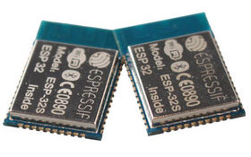
ESP8266 ESP-201 module - antenna troubleshooting
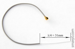
ESP-201 external monopole antenna
(λ - 2.4GHz wavelength - 125mm)
ESP-201 module has two antenna options:
- on-board so-called "inverted F antenna"
- external antenna plugged into U.FL connector
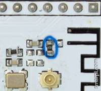
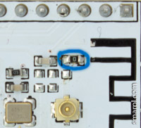
The antennas are not intended to work simultaneously. By default ESP-201 board has external antenna selected. To use on-board antenna, the jumper (0 Ohm SMD resistor) should be resoldered as shown on the following pictures.
External antenna selected (default)
On-board antenna selected
So far, so good.
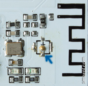
Unfortunately the module has very poor WiFi range with the external antenna. After a quick inspection I found that the U.FL connector is placed incorrectly and in fact is SHORTED. The following picture shows what exactly is going on - central pin of the connector is soldered to ground.
(outer part of connector is removed)
The solution is simple - resolder the U.FL connector rotated by 180 degrees.
Note, this is not a kind of fundamental design problem, It's a trivial manufacturing bug. Modules from newer batches may be not affected. Check the connector of your module for a short circuit with a multimeter before doing any soldering work.
Comments
bcatalin
Tue, 02/10/2015 - 05:16
Permalink
Cool findings ! I am waiting
Cool findings ! I am waiting my ESP-201 to check if there is the same error is present. After re-soldering the U.FL connector did WiFi improved ? How big is the range now ?
smarpldotcom
Tue, 02/10/2015 - 16:09
Permalink
Yes, the external antenna now
Yes, the external antenna now works as expected.
I didn't measure the exact range, just made a simple comparison test between two ESP-201 modules with different antennas. Seems the external antenna performs a few dB better than on-board one.
Measuring distance - approximately 7 meters
X-axis - time
Yellow line - ESP-201 with external antenna
Blue line - ESP-201 with on-board antenna
Anonymous
Fri, 02/13/2015 - 11:59
Permalink
Hi,
Hi,
new module ESP8266-201 just arrive !
coming with a real old firmware and the IPX connector in wrong position :(
i successful flash the 00170901 AT firmware from Espressif with bootlader : it work
then now, i try to do an update from cloud (AT+CIUPDATE) : seem working with the 4 steps, but after reboot, only garbage and "MEMORY FAIL" message .. not usable :(
don't know if the last AT firmware (0.20 or more) is compatible with this SPI Flash ..?
any advice please ?
regards
Phil
bobo
Tue, 03/10/2015 - 07:39
Permalink
I have this module but not
I have this module but not worging, I check your pictures, I have reversed crystal, I rotated but not working. I think that this is worst module from ESP series
Stuart Davies
Sun, 06/07/2015 - 13:39
Permalink
Hi
Hi
I have just got mine working. I had a problem with the external antenna, it fell OFF. I soldered it back on and now it seems to be working.
The picture of the external antenna in your article, is that the finished antenna or do I need to solder 31mm or 125mm additional wire to it? What is the best way to improve reception?
I have an Arduino sketch that writes the signal strength to the Serial port. I am getting -79, -80, -78 ,,, Do you know if this is a good signal or a poor one. I assume the closer to ZERO the better?
Adding a 125mm does not seen to change much..
The WiFi analyser for Android on my LG G3 reports a -70 from the same spot!
I purchased this board from 'Bang Good' because it was breadboard friendly (apart from the programming header which I swapped to the other side of the board) , it was £3. Do you think a more expensive version would give better reception.
It has taken me some time to get this thing working and now I have an Arduino IDE set up and working I would like to put a IOT together.
Thanks
Stuart
Add new comment