ESP8266 ESP-04 tips and tricks
 Overview
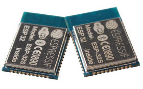
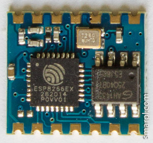
ESP-04 module is one of the smallest ESP8266 boards. Its size is approximately 12.5x14.5mm i. e. smaller than 1 euro coin. It is Surface Mount Technology (SMT) module with 2mm pad spacing. The module has no on-board antenna.
Seven GPIO pins are broken out: GPIO0, GPIO2, GPIO12, GPIO13, GPIO14, GPIO15, GPIO16. Not a record, but it's enough for many projects.
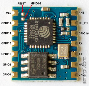
ESP-04 "external interface" consists of 14 pads arranged in two rows on the opposite sides of the board. For some reason the manufacturer left one pad not connected anywhere. (Why not to make one more GPIO pin available?)
Where is Reset pin?
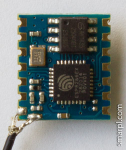
Reset pin (ESP8266EX pin 32) is essential for flashing new firmware to the ESP8266 module. Unlike most ESP8266 modules, ESP-04 has no reset pin routed to the external interface pins. The reset pin can be found in the top left corner of the board near the Vcc pad (see picture below). It is fairly easy to solder a thin copper wire to it.
If you use deep sleep mode in your ESP8266 project, GPIO16 should be connected to RESET (preferably through resistor) for the successful wake-up. ESP-04 is ready for this scenario - there are unpopulated pads for the SMD resistor or jumper between GPIO16 and RESET (marked with red arrows below).
Antenna connection
ESP-04 has output to the external antenna, it's one of the outermost pads. But there is no GND pad next to it, so connecting coaxial antenna cable can be tricky.
The following images show a way to connect RF antenna cable to the ESP-04 board.
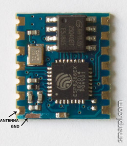
(scratch blue lacquer coating to reach GND track)
Add new comment