ESP8266 ESP-201 module - first impressions
 Overview
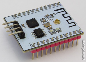
I've been experimenting with different ESP8266 (mostly ESP-01) modules already for some time. As soon as ESP-201 became available I ordered them and yesterday received the long awaited package. And I was not disappointed. The ESP-201 module is a really good choice for prototyping ESP8266 projects.
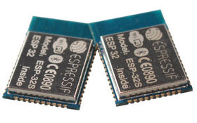
The size of the board is 25x35mm, totally it has 26 pins with 0.1' (2.54mm) pin spacing. ESP-201 is equipped with on-board antenna and U.FL connector for the external antenna, which also was included in package. See more details on ESP-201 antenna troubleshooting.
Compared to ESP-12 this module has 6 more pins broken out - D0, D1, D2, D3, CLK, CMD (GPIO6-GPIO11). But only two of them (D2, D3) can be used as regular GPIOs after slight hardware modification.
As well as other ESP modules the ESP-201 comes with AT firmware preloaded (mine has 0019000902 version). The vendor appears to be "http://goouuu.com" instead of "ai-thinker" in ESP-01..ESP-12.
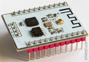
Unfortunately some soldering required to make the module breadboard friendly. The UART pins should be moved to the other PCB side. See pictures below.
Before
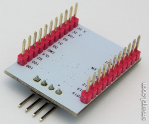
After
First run
GPIO15 should be pulled down at startup to switch module into boot from flash mode. Other connections are the same as with ESP-01 module (RX<->TX, TX<->RX, RESET<->RTS, GPIO0<->DTR).
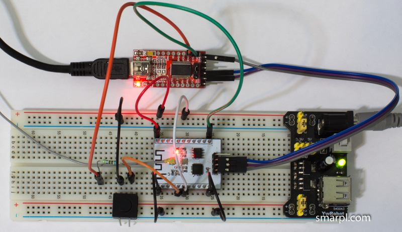
Click to view large image
Pin reference
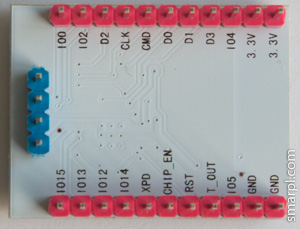
One more issue with ESP-201 module is related to pin labels - they are printed on the bottom side of the board only. So it's hard to find the right pin without documentation when the module is plugged into breadboard.
I created a cheat sheet to make locating pins easier. This looks more like a draft now. I'm going to improve it by adding all possible pin functions.
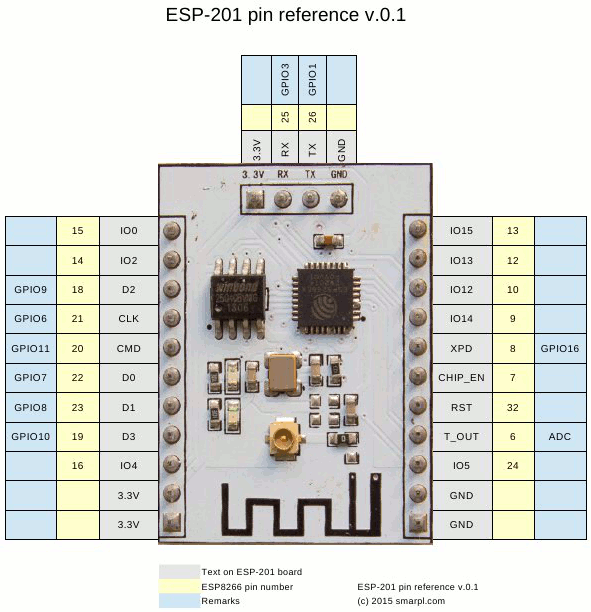
Download ESP-201 pin reference in pdf
Comments
jenny
Thu, 02/12/2015 - 01:20
Permalink
How to use this ESP-201
How to use this ESP-201 module for only serial communication (RCX and TRX) with arduino? Any extra wiring?? Also, TRX and RCX pin of this module are 3.3v but you have connected them direcly without any voltage divider at least for Module RCX pin. Is it OK? Safe for module??
smarpldotcom
Thu, 02/12/2015 - 08:11
Permalink
Exactly the same way as ESP
Exactly the same way as ESP-01, additionally connect GPIO15 to ground. Yes, you're right, the ESP8266 is not 5V tolerant, and for 5V arduino boards level shifter or divider is required.
In particular case the USB-Serial converter has TTL (3.3V) level output, so such connection is safe.
Ger
Fri, 02/13/2015 - 13:28
Permalink
What is the easy way to
What is the easy way to change the UART pins
Anonymous
Mon, 02/16/2015 - 05:29
Permalink
Out of the box, what is the
Out of the box, what is the baud rate needed to talk to the ESP-201? I connect directly with an FTDI dongle but am getting no response.
cheers
George
Thu, 02/19/2015 - 09:43
Permalink
The ESP-201's I purchased ran
The ESP-201's I purchased ran at 76800 baud.
Markus
Thu, 08/06/2015 - 03:54
Permalink
You can easily run 3 to 4
You can easily run 3 to 4 times that.
Alvaro
Wed, 02/25/2015 - 17:39
Permalink
Hi,
Hi,
The ADC pin is input? It is possible to read from a LDR?
Thanks,
Alvaro
smarpldotcom
Thu, 02/26/2015 - 17:28
Permalink
Exactly. But pay attention
the plant doctor
Thu, 11/19/2015 - 12:35
Permalink
you can connect several ldr
you can connect several ldr light sensors if you want. or any analog sensor. check it out with examples; http://www.instructables.com/id/ESP8266-with-Multiple-Analog-Sensors/
thank you for a good intro to esp201 board.!
shail
Fri, 02/27/2015 - 21:15
Permalink
Is there any way to check if
Is there any way to check if ESP-8266 boards are not defective. I am using USB TTL serial adapter. It has five pins. 5V, RX, TX, GND, 3.3V.
I've connected in following way
RX<->TX, TX<->RX, GPIO0<->3.3V, GPIO15 <-> GND
I don't see any response in minicom, I've also tried coolterm. I've tried 9600, 11500 baud rates. There is no way to set 76800 in both software.
smarpldotcom
Sat, 02/28/2015 - 04:57
Permalink
Don't forget to connect CHIP
Thilo
Tue, 03/24/2015 - 11:15
Permalink
Hi, mine had 19200 Baud, I've
Hi, mine had 19200 Baud, I've connected 3V3-3V3, GND-GND, RX-TX, TX-RX, 1015(IO15?)-GND, 100(IO0)-GND, CHP_EK(EN?)-3V3 and was able to flash with the NodeMCU Firmware Programmer
Thakshak
Mon, 04/27/2015 - 00:12
Permalink
I wanted to buy this... But
I wanted to buy this... But was in btw this and esp12
How many pins can i use as regular gpios in this esp201.
Thanks...
eta-sys
Wed, 04/29/2015 - 03:15
Permalink
I'v ordered ESP-201 from here
I'v ordered ESP-201 from here: http://www.aliexpress.com/item/5pcs-ESP8266-serial-WIFI-Industrial-stable-version-A-full-test-board-Full-IO-leads-ESP-201/32303950435.html
Works fine. No antenna problems. No need to ground GPIO15 to chat with module. Version 00170901. RS speed 115200. Needs AT+RST after mode-selecting, before WiFi connection set. Embedded aps didn't check yet while received yesterday.
Mike
Tue, 06/09/2015 - 08:12
Permalink
Hi,
Hi,
I cannot find any details on the question what size of EEPROM (Mbit/MByte) is on your ESP-201?
And wanted to say thanks for your article.
smarpldotcom
Tue, 06/09/2015 - 19:38
Permalink
My ESP-201 modules came with
Dougal Campbell
Mon, 06/22/2015 - 08:31
Permalink
Spent some time yesterday
Spent some time yesterday trying to get up and running with an ESP-201, with mixed results. I *did* at least get it to respond to AT commands at one point. Then I tried flashing a program via the Arduino IDE, it appeared to attempt to flash in two parts, but failed on the second.
After that, I was unsuccessful in even getting serial comms working again.
I had the IDE set to "Generic ESP8266", Flash size 512K, CPU Freq 80MHz, Upload speed 115200 (which is where I had my successful serial AT comms earlier).
I tried re-wiring and re-flashing a few times, but on my last try all I got was "warning: espcomm_sync failed
error: espcomm_open failed".
I seem to sometimes see conflicting information about whether GPIO0 and GPIO15 should be pulled up or down for certain functions. I have both CHP_EK and XCD pulled up to 3.3V.
Also, some guides show connections for DTR and RTS, but my FTDI Friend only has RTS available by default (with a solder jumper allowing a choice between DTR and RTS). I've just discovered that I can solder a wire directly to the DTR pad in order to get access to both lines simultaneously, but that will have to wait until I get free time again. But then again, some guides don't use those control lines at all.
I'll have to try to keep some notes as I go along and figure more about how things fit together...
What I'd like to see, but I'm not sure I have, is a guide that shows the *absolute minimum* requirements of what ESP pins need to be in what state for Serial AT comms vs Programming.
Dougal Campbell
Mon, 06/22/2015 - 22:49
Permalink
Successfully flashed tonight!
Successfully flashed tonight! Nothing fancy, just your standard LED blink. But at least now I passed the first hurdle, and I can work on something more real.
Pranav Sharma
Thu, 07/16/2015 - 11:48
Permalink
hey hi, i am having the same
hey hi, i am having the same problem as u have or had ?
so i was wondering if you found the solution then can u help me ?
i am using the latest version of Arduino IDE and Generic ESP8266
And also i get a message on Serial Monitor "AT+RST"
i also wanted to know that i m using....ARDUINO UNO and get it directly Connected with ESP8266,
so AnyOther SUpporting hardware is;nt required ? right ?
help please !!!
Babu Biri
Wed, 10/07/2015 - 03:10
Permalink
Dear
Dear
I am facing exactly the same problem, i tried all like pulling down io15 and pull ip chk, but in vain
I will be grateful if you tell us how you did it?
Juergen
Thu, 07/09/2015 - 08:27
Permalink
I get the followinh message
I get the followinh message from nodemcu flasher:
Note:Serial port connected.
Note:Begin find ESP8266.
Note:ESP8266 ACK success.
Error:Read ESP8266 register timeout.
What do I wrong?
Mark Punkt
Fri, 07/17/2015 - 02:15
Permalink
Hi,
Hi,
i successfully use the ESP-201 to switch a 2-channel-relay board via wifi and even work as a client to update some webdata at the same time.
Now i wanted to switch more relays.
In the picture shown above there are GPIO07 - GPIO10 available on the Pins D0 - D3.
I work with the Arduino IDE - but i don't get it to work that i can use these Dx-Pins to work as GPIOs (Output).
I tried with the pinMode-command - but no success.
Even the GPIO0 i do not get to work successfully.
Do you have any hints how i can get these Pins to work as GPIO?
thanks in advance...
JoeO
Fri, 08/14/2015 - 10:31
Permalink
The best way to use and learn
The best way to use and learn about the ESP-201 is by using the SDK that it was designed for. The SDK has 2 LEDs, a buzzer, a DHT11 and a SPDT relay rated at 10 amps. All signals have pinned breakouts so you can prototype with them off of the board. I have downloaded to it using the Arduino IDE 1.6.4.
For $15 you can not beat it. I reordered and now have a total of 3.
http://www.ebay.com/itm/ESP8266-Serial-Wireless-Wifi-Module-Develop-Board-8266-SDK-Development-GOOD-/400914764132?pt=LH_DefaultDomain_0&hash=item5d5861d164
Anonymous
Sat, 08/22/2015 - 13:07
Permalink
I get 2 piece ESP-201 from
I get 2 piece ESP-201 from http://www.aliexpress.com/item/ESP8266-serial-WIFI-Industrial-stable-version-A-full-test-board-Full-IO-leads-ESP-201-IPX/32290998969.html and use PL-2303HXC to connect from ubuntu 14.04. I try many time with esptools.py, arduino IDE 1.6.5 and EXPlorer.
Connect:
Tx -> Rx on PL2303
Rx -> Tx
GND -> GND
VCC -> 3.3V (onother power)
IO0 -> GND
IO15 -> GND
Chip_EN -> VCC
but can not connect, also try with all boudrate listed on ESPlorer and Arduino IDE.
But with Putty, when I use 115200, return "lb.lrl" ( code "6C 62 0E 6C 72 6C")
with Putty, I change IO0 to VCC, and float IO15, return "nn|..`." (code "6E 6E 7C 90 92 60 02")
when I change to another boud rate, some another code print out.
all time can not enter anything to Putty
Anyone can suggest me something to solve? Ihave try one day to change many speed but no result.
mohsen
Tue, 09/01/2015 - 22:53
Permalink
how to flash esp201 for use
how to flash esp201 for use AT Command ?
what primary baud rate in esp201?
how to connect esp201 to arduino and control led?
Marcus Behrens
Sun, 01/31/2016 - 03:13
Permalink
My 201 module worked right
My 201 module worked right away with the following setup:
3.3v connected to regulator output of 3.3v
GND connected to ground
CHIP_EN connected to 3.3v
IO15 connected to GND
IO0 pulled doen to ground with 10k resistor and pulled up to 3.3v with button when button is pressed
RST pulled up to 3.3v with 10 resistor and pulled down to GND with button when button is pressed
TX to RX on my FTDI module with chip FT232RL (on a hacklace device switched to 3.3v mode from fab4u)
RX to TX on my FTDI module
GND to GND on my FTDI module
USB of FTDI module to USB on my computer
FTDI driver installed on my Windows 10 computer and showing up as COM6
Arduino IDE 1.6.7 installed and serial monitor on COM6
My module shows the boot details when pressing reset or powering on even at 74880 baud:
reset leads to "ets Jan 8 2013,rst cause:2, boot mode:(1,7)"
power off and back on to "ets Jan 8 2013,rst cause:1, boot mode:(1,0)"
When switching to 115200 baud only gibberish shows up on boot but when pressing the button that pulls IO0 up to 3.3v then I can use AT commands to talk to the thing:
Ai-Thinker Technology Co. Ltd.
ready
AT+GMR
AT version:0.25.0.0(Jun 5 2015 16:27:16)
SDK version:1.1.1
Ai-Thinker Technology Co. Ltd.
Jun 5 2015 23:07:20
(Set Wifi mode to both Access Point and STAtion:)
AT+CWMODE=3
OK
AT+RST
OK
(List Access Points:)
AT+CWLAP
+CWLAP:(3,"behrens",-70,"5c:49:79:62:bd:6a",11)
OK
Thanks for the good report - without it it would have been difficult. I also looked at https://atulnivyadav.wordpress.com/2015/07/18/iot-encounter-with-esp8266... which gave more details on the wiring.
Ali
Sat, 04/30/2016 - 13:57
Permalink
Hi
Hi
what is pin XPD?
where is a pin CH_PD?
Lotus49
Mon, 06/13/2016 - 13:20
Permalink
Are there any benefits to the
Are there any benefits to the ESP201 compared to the NodeMCU dev boards? The latter are so cheap (less than £3 inc P&P) and since they break out all the pins on the ESP12E and have builtin USB-TTL level shifter, they seem very good value to me.
Steve
Thu, 10/13/2016 - 04:34
Permalink
I have an FTDI dongle with a
I have an FTDI dongle with a jumper for 3.3v (or 5v) operation. I connected my 201 as follows:
GND -> GND
VCC -> 3.3v
TXD -> RX
RXD -> TX
DTR -> IO0
RST -> VCC (or GND to reset)
CHIP_EN -> VCC
IO15 -> GND
With these settings, the serial monitor in the Arduino IDE (v 1.6.11) can connect to it at 74880 baud.
ltwfasr
Sun, 05/19/2019 - 14:47
Permalink
Спасибо за информацию!!!!!
Спасибо за информацию!!!!!
Add new comment