Submitted by smarpldotcom on Tue, 10/11/2016 - 05:35
ESP32 based modules ESP-32S finally available for ordering.
Reserved mine today. I'm very curious to test if the new chip is really so cool as described.
Submitted by smarpldotcom on Fri, 03/27/2015 - 15:06
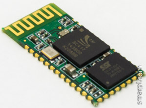
 These small and cheap CSR BC417143 based wireless Bluetooth transceiver modules are widely used in all kind of embedded projects. They are intended for serial communication and preloaded with serial port profile (SPP) firmware.
The module has user configurable parameters like Device name, Pairing PIN and Serial speed. In most cases the default values of these parameters should be changed (at least Pairing PIN code) to suit your application. It is done by entering special AT commands when the module it is not remotely connected to any other bluetooth device.
Late in 2013 I've created this bluetooth module configuration tool to simplify bluetooth module configuration by avoid dealing with AT commands. So it's fairly old but still useful.
Bluetooth module configuration tool (hc04conf) is a command line utility for quick an easy configuration of Bluetooth transceiver modules connected to the serial port (or USB to serial converter) of your machine. It works on Windows, Linux and Mac OS X systems.
Submitted by smarpldotcom on Fri, 03/20/2015 - 15:28
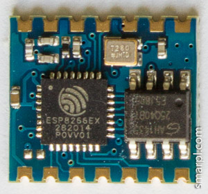
 ESP-04 module is one of the smallest ESP8266 boards. Its size is approximately 12.5x14.5mm i. e. smaller than 1 euro coin. It is Surface Mount Technology (SMT) module with 2mm pad spacing. The module has no on-board antenna.
Seven GPIO pins are broken out: GPIO0, GPIO2, GPIO12, GPIO13, GPIO14, GPIO15, GPIO16. Not a record, but it's enough for many projects.
ESP-04 "external interface" consists of 14 pads arranged in two rows on the opposite sides of the board. For some reason the manufacturer left one pad not connected anywhere. (Why not to make one more GPIO pin available?)
Submitted by smarpldotcom on Fri, 02/06/2015 - 16:04
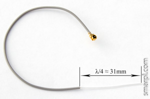
 ESP-201 external monopole antenna
(λ - 2.4GHz wavelength - 125mm)
ESP-201 module has two antenna options:
- on-board so-called "inverted F antenna"
- external antenna plugged into U.FL connector
The antennas are not intended to work simultaneously. By default ESP-201 board has external antenna selected. To use on-board antenna, the jumper (0 Ohm SMD resistor) should be resoldered as shown on the following pictures.
Submitted by smarpldotcom on Tue, 02/03/2015 - 19:50
Despite the fact ESP-201 module has D0, D1, D2, D3, CLK, CMD (GPIO6-GPIO11) pins broken out they provide interface to flash chip and cannot be used as regular GPIOs.
An attempt to assign GPIO function to any of these pins, e. g.
PIN_FUNC_SELECT(PERIPHS_IO_MUX_SD_DATA2_U, FUNC_GPIO9); // Select GPIO function for SD_DATA2
will definitely cause module hangup or reboot during the subsequent flash access.
Since it is supported by both ESP8266 and flash chip (25Q40B) the Quad I/O SPI flash interface can be downgraded to Dual I/O SPI thus freeing two data lines (SD_DATA2 and SD_DATA3) and making them available as GPIOs (GPIO9 and GPIO10, marked as D2 and D3 on ESP-201 board).
Pages