ESP8266 ESP-201 module - freeing up GPIO9 and GPIO10
Despite the fact ESP-201 module has D0, D1, D2, D3, CLK, CMD (GPIO6-GPIO11) pins broken out they provide interface to flash chip and cannot be used as regular GPIOs.
An attempt to assign GPIO function to any of these pins, e. g.
PIN_FUNC_SELECT(PERIPHS_IO_MUX_SD_DATA2_U, FUNC_GPIO9); // Select GPIO function for SD_DATA2will definitely cause module hangup or reboot during the subsequent flash access.
Since it is supported by both ESP8266 and flash chip (25Q40B) the Quad I/O SPI flash interface can be downgraded to Dual I/O SPI thus freeing two data lines (SD_DATA2 and SD_DATA3) and making them available as GPIOs (GPIO9 and GPIO10, marked as D2 and D3 on ESP-201 board).
The following schematics diagram shows required changes (In Dual I/O SPI mode the D2 and D3 flash pins implement Write-protect (/WP), and Hold (/HOLD) functions, so we need to pull-up them).

The similar modification can be carried out on the other ESP8266 modules (ESP-01, etc) but it's more difficult as requires somehow to break out GPIO9 and GPIO10.
Hardware modification
Warning
The procedure described next requires good soldering skills. Improper soldering can cause permanent damage to your module.
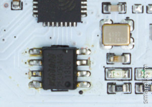
1. Desolder the flash chip
2. Carefully using sharp blade cut the pin pads as shown below
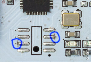
3. Remove the pin pads (Heat them with soldering iron for about 5 seconds, then apply slight pressure)
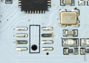
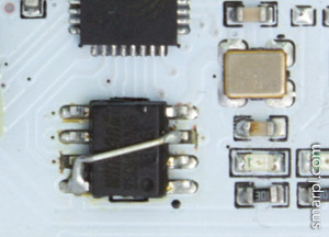
4. Put the flash chip back
5. Connect floating pins 3 and 7 to Vcc (i. e. pin 8) with a thin wire
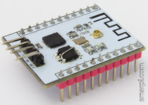
6. Ready to prototype with GPIO9 and GPIO10 available
Flashing firmware
Changes to firmware required to select Dual I/O mode instead of Quad I/O mode. Otherwise the module will not boot. Depending on tools used to build and flash your firmware the required steps may differ.
If the firmware is created with "esptool.py elf2image" then you need to add "--flash_mode dio" option.
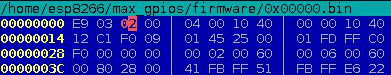
$(ESPTOOL) elf2image --flash_mode dio ...Alternatively patch the 0x00000.bin file manually - change low nibble of the third byte form 0x0 to 0x2
If using some GUI tool look for "DIO" option.
Example code using GPIO9 and GPIO10
// Note, the following code will not work as expected on unmodified hardware

// assign SD_DATA2 and SD_DATA2 GPIO function
PIN_FUNC_SELECT(PERIPHS_IO_MUX_SD_DATA2_U, FUNC_GPIO9);
PIN_FUNC_SELECT(PERIPHS_IO_MUX_SD_DATA3_U, FUNC_GPIO10);

// set GPIO9 and GPIO10 low
gpio_output_set(0, BIT9, BIT9, 0);
gpio_output_set(0, BIT10, BIT10, 0);

// set GPIO9 and GPIO10 high
gpio_output_set(BIT9, 0, BIT9, 0);
gpio_output_set(BIT10, 0, BIT10, 0);
Comments
rudi
Thu, 06/25/2015 - 10:36
Permalink
txs for your work!
txs for your work!
nice and fine documented.
have linked it to bbs.espressif.com
best wishes
rudi ;-)
Adex
Sat, 07/18/2015 - 13:25
Permalink
Already published this method
Already published this method in January 2015 for ESP01
http://www.esp8266.com/viewtopic.php?f=13&t=1216
ESPecially
Tue, 06/28/2016 - 09:55
Permalink
I think the traces for gpio9
I think the traces for gpio9 and -10 of an ESP-01 are on the back of the PCB and can be modded without removing the flash chip...
stefano
Tue, 07/26/2016 - 10:08
Permalink
Work perfect on Lolin NodeLua
Work perfect on Lolin NodeLua except that GPIO10 is on CK pin (!)
Many thanks, Stefano
marek
Thu, 09/22/2016 - 03:09
Permalink
Would it not be easier to
Would it not be easier to just bend the pins on flash upwards and connect them to pull up? No need to cut and remove pads.
Add new comment