Add new comment
ESP8266 ESP-201 module - first impressions
 Overview
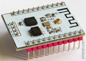
I've been experimenting with different ESP8266 (mostly ESP-01) modules already for some time. As soon as ESP-201 became available I ordered them and yesterday received the long awaited package. And I was not disappointed. The ESP-201 module is a really good choice for prototyping ESP8266 projects.
The size of the board is 25x35mm, totally it has 26 pins with 0.1' (2.54mm) pin spacing. ESP-201 is equipped with on-board antenna and U.FL connector for the external antenna, which also was included in package. See more details on ESP-201 antenna troubleshooting.
Compared to ESP-12 this module has 6 more pins broken out - D0, D1, D2, D3, CLK, CMD (GPIO6-GPIO11). But only two of them (D2, D3) can be used as regular GPIOs after slight hardware modification.
As well as other ESP modules the ESP-201 comes with AT firmware preloaded (mine has 0019000902 version). The vendor appears to be "http://goouuu.com" instead of "ai-thinker" in ESP-01..ESP-12.
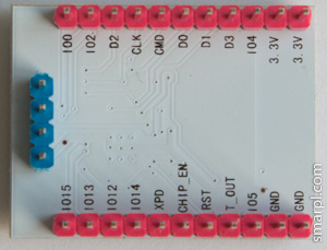
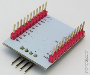
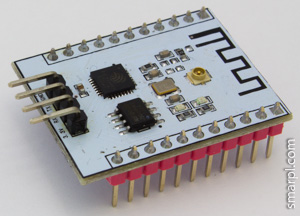
Unfortunately some soldering required to make the module breadboard friendly. The UART pins should be moved to the other PCB side. See pictures below.
Before
After
First run
GPIO15 should be pulled down at startup to switch module into boot from flash mode. Other connections are the same as with ESP-01 module (RX<->TX, TX<->RX, RESET<->RTS, GPIO0<->DTR).
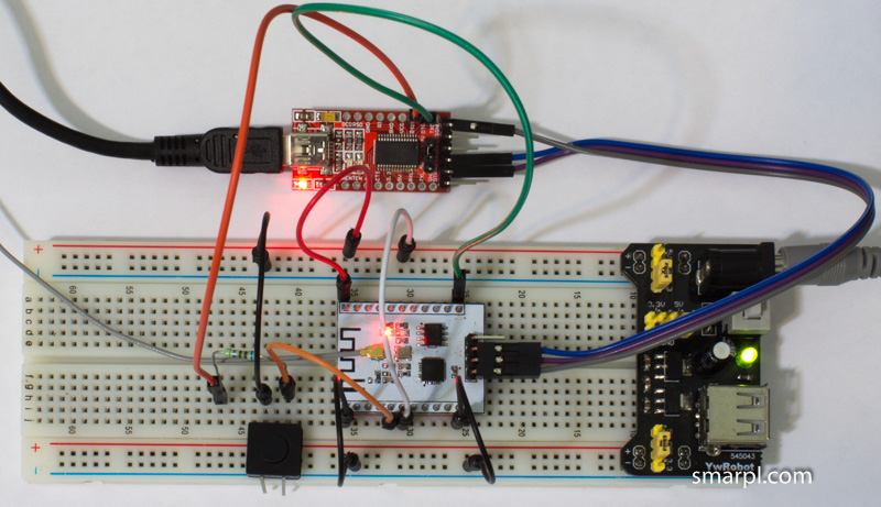
Click to view large image
Pin reference
One more issue with ESP-201 module is related to pin labels - they are printed on the bottom side of the board only. So it's hard to find the right pin without documentation when the module is plugged into breadboard.
I created a cheat sheet to make locating pins easier. This looks more like a draft now. I'm going to improve it by adding all possible pin functions.
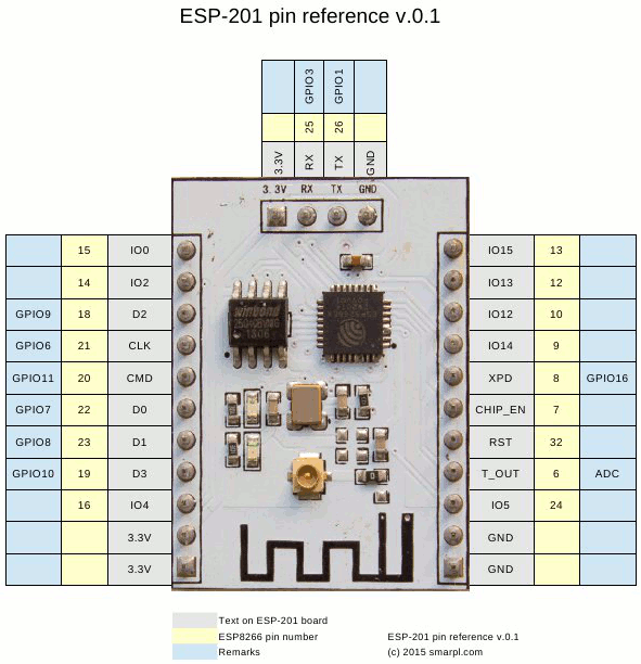
Download ESP-201 pin reference in pdf